My Account     Contact Us     Cart

Defining the Projection or Projecting the Data?

Have you ever imported data that doesn’t quite line up how you’d expect? It may be that you’ve fallen victim to a common workflow error when importing GIS data. Some file types such as CSV can be used for GIS data but don’t contain coordinate system information. When you are importing data from this format, you first have to define the correct coordinate system.

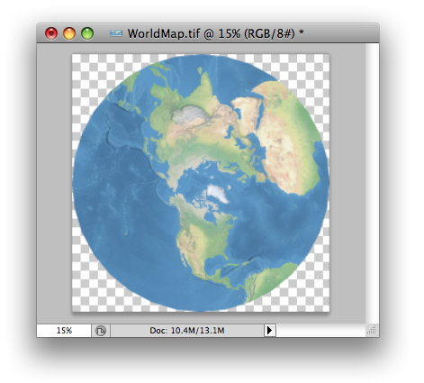
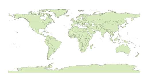
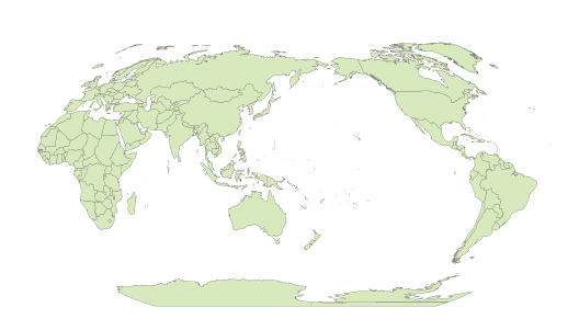
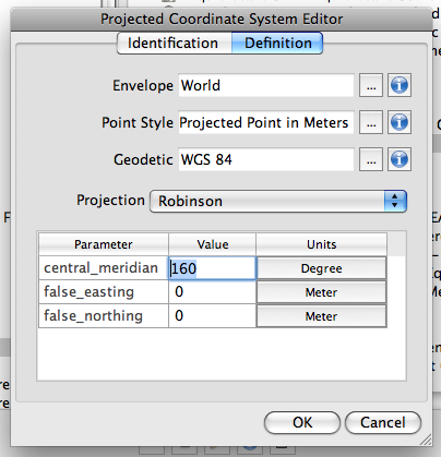
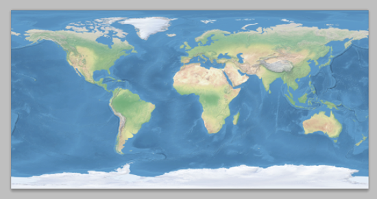
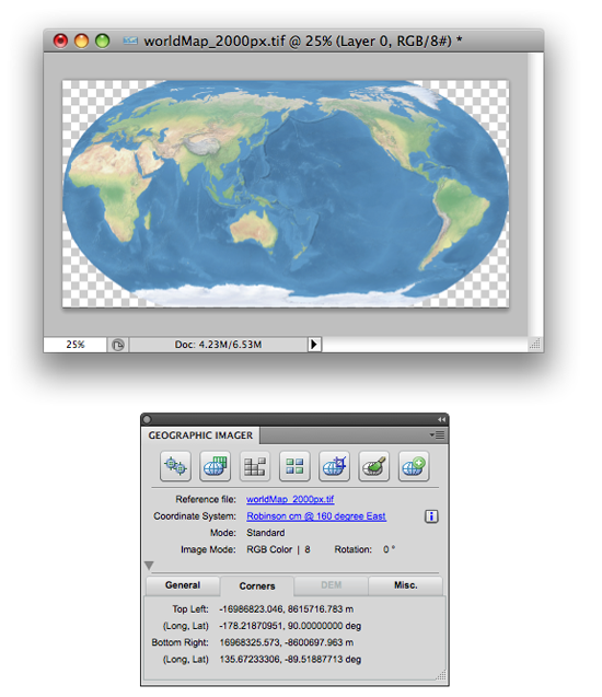
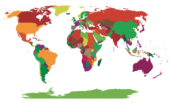
In this example, we’re going to look at the common mistakes people make and how to avoid them. We’ll start with a world map in the Robinson projection.

Robinson map
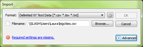
We have a CSV file containing points for large cities that we’d like to add to the map. We know from our data source that the CSV uses the WGS84 coordinate system. After selecting the file for import, the MAPublisher Import dialog box helpfully notifies us that some required settings are missing. We’ll click the blue ‘Required settings are missing’ link to continue.

required settings
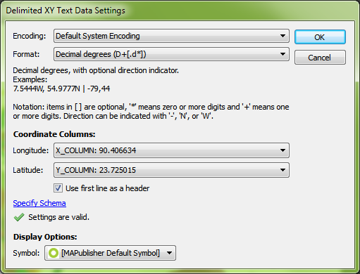
Setting up the import, the coordinate column settings are easy since we have an X_COLUMN and a Y_COLUMN, but we can’t forget to check that the format is correct. The default is Projected units, but we know the file uses WGS84, and can tell by the numbers in the column that the coordinates are in decimal degrees, so we’ll change the format to reflect this information and click OK.

csv correct settings
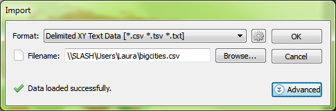
Back at the import window, we see the message ‘Data loaded successfully’. Great! Let’s click OK and add the large cities to the map.

csv settings are ok
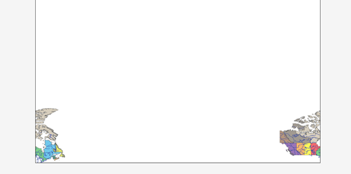
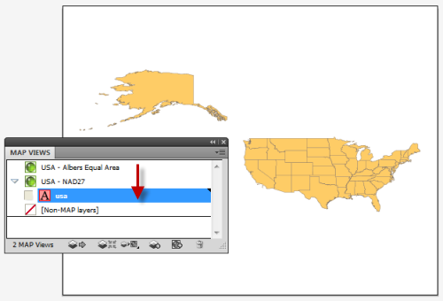
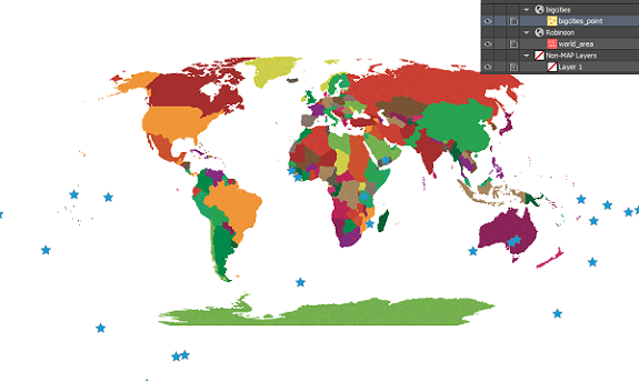
The data has been imported but the result isn’t what we expected. The new layer has been added to a new MAP View, so let’s try dragging it into the Robinson MAP View with the world map.

import incorrect
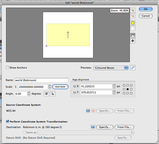
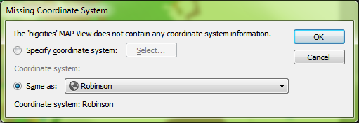
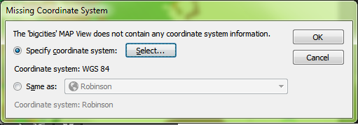
We get a prompt saying that there isn’t any coordinate system information. We want it to be in Robinson like the rest of the map so we’re going to leave the default setting of Same as: Robinson.

coordinate system undefined
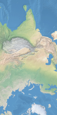
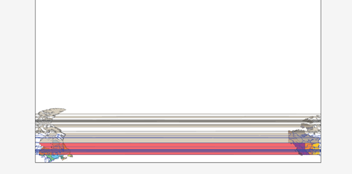
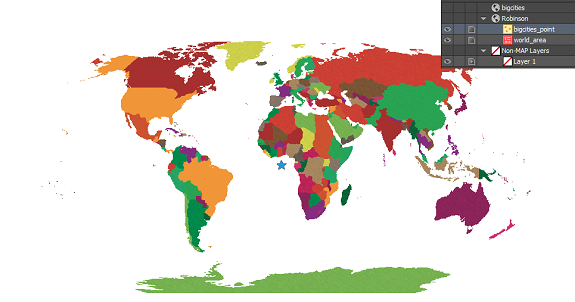
The data has moved, but it still doesn’t look like we were expecting. Where did we go wrong here?

transformation incorrectThere are actually two places in the workflow where we could have avoided this common mistake. When we dragged the point layer into the Robinson MAP View, the pop-up dialog box prompted that a coordinate system wasn’t specified. We specified Same as: Robinson, thinking this was the correct choice, but we had already determined during import that the CSV was in WGS84. What we should have done here was to specify the coordinate system as WGS84.

missing coordinates correctThe other place where we could have avoided this error was right after setting up the CSV file for import. In MAPublisher 9.4, there’s a new button on the Import dialog box that allows you to see more detailed information about files being imported. By clicking the Advanced button in the Import dialog box, we would have noticed that there was no coordinate system specified.

advanced import window
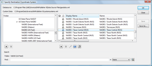
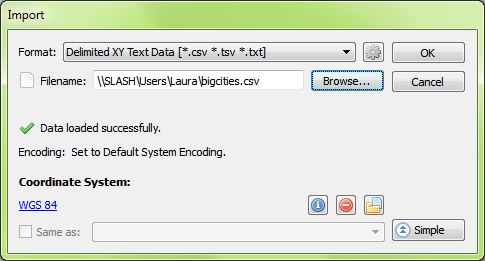
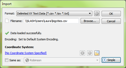
Even here, it might have been tempting to choose Same as: Robinson to add it to the Robinson MAP View, but this would import the points exactly the same as before – all in one location in the middle of the map. Instead, what we want to do is click the blue ‘No Coordinate System Specified’ link and choose WGS84. After this is set up, we’ll click OK to add the data to the map.

correct import settingsThe data still isn’t quite right – it looks the same as when we first imported it. But again we notice that it has been imported into a new MAP View, so we’re going to drag the layer into the Robinson MAP View and see what happens.

import incorrect
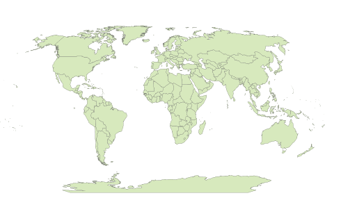
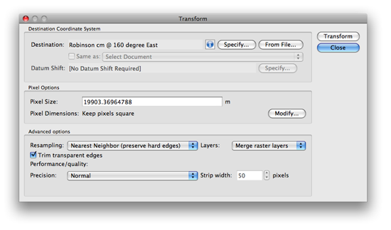
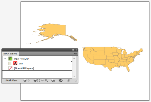
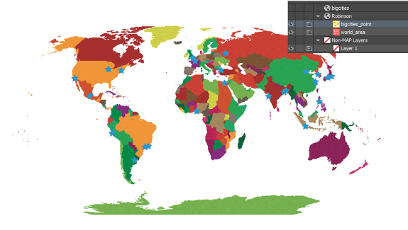
Perfect! By assigning the correct coordinate system to the data during import, the points have been imported correctly!

correct map with pointsMistakes during data import are common amongst GIS users, especially those who are just starting out. In the first scenario, when we imported the CSV and added the data directly to the Robinson MAP View, we thought we were telling MAPublisher that we’d like it to match up with the map. What we really did was tell MAPublisher that the data was already in the Robinson projection, even though we knew it was in WGS84. What we should have done first was to define the projection by telling MAPublisher what coordinate system the data is already using. Once MAPublisher knows what system the data is starting in, we can then ask it to project or transform the data into the coordinate system that we’d like to use.

When working with data that doesn’t have coordinate systems already defined, it is very important to follow the workflow in the correct order to avoid frustration when the data doesn’t line up as expected. Always check your sources when using data that isn’t defined, and make sure you’re assigning the correct coordinate system before performing any transformations or projections.

New Transformation Method for World Maps in Geographic Imager 3.2

When transforming a world image, there may be artifacts created by the Geographic Imager transformation engine. Below are the results of a WGS84 world image transformed into a Stereographic projection.

Geographic Imager 3.1 transformation result

When we zoom into the problematic area, you can see up close how some artifacts affect the image after the transformation was performed.

Geographic Imager 3.0 transformation result 2

To solve this issue, we are introducing a new projection method called Maximum: World Projection in Geographic Imager 3.2.

We are going to use the same world image used with the previous example and transform it into the stereographic projection. Take a close look at the Advanced Options.

Geographic Imager 3.2: Transformation Dialog box

Under the Performance/quality section, select Maximum / World Projections from the Precision drop-down list and click OK.

Geographic Imager 3.2: Maximum / World Projections option

Below is the result of the transformation with the new method available in Geographic Imager 3.2.

Geographic Imager 3.2 transformation result

Let’s take a close look at the same area where the problem happened with the previous version of Geographic Imager. Now the transformed image does not contain any artifacts.

Geographic Imager 3.2: result (zoom in!)

This option is available since Geographic Imager 3.2. The official version of Geographic Imager 3.2 is available now.

Creating a Custom Coordinate System from a Predefined Coordinate System

When transforming a world map in a geodetic system (such as WGS84) to a predefined projection (such as Robinson) using MAPublisher, the central meridian of the predefined projection should be set to 0 degree longitude as shown below.

Image 1: world map in WGS84

World map in WGS84 geodetic system

Image 2: world map in a predefined Robinson Projection

World map with the Robinson Projection with default settings

However, you might want to have a map with a different region centred on your map. For example, Image 3 below shows a world map with a part of Asia centred. In this case, the central meridian was set to 160 degrees East.

Image 3: world map in a custom Robinson Projection with a central meridian value set to 160 degree East

World map in a custom Robinson projection

Today we’ll introduce how to create a custom coordinate system by modifying a predefined coordinate system. We’ll use an example using a GIS dataset world.mif available in the MAPublisher Tutorial folder. We are going to transform a world map to a custom central meridian value with the Robinson projection.

Step 0 : import the “world.mif” file from MAPublisher tutorial folder.

step0:: import World.mif

Step 1 : Open the MAP View Editor window from the MAP Views panel.

In the MAP View Editor window, you can see that the scale of the map, position of the map extent with respect to the current document extent, and most importantly the current coordinate system assigned to the MAP View.

step 1: MAP View Editor window

We are going to transform the MAP View from WGS84 to the Robinson projection with a custom central meridian value. Check the “Perform cordinate System Transformation option.

Click the Specify button under the “Perform Coordinate System Transformation” section. It will open the “Specify Destination Coordinate System” dialog box.


Step 2: Creating a custom coordinate system with the Robinson projection

We are going to create a custom coordinate system based on the Robinson projection by modifying the existing Robinson projection. Find the existing Robinson projection from the list.

On the left side, navigate to Coordinate system > Projected > World. Highlight the folder “World”. You will see the list of the predefined coordinate systems available on the right side of the window. Find the “Robinson” and highlight it.

Step 2: Finding the predefined Robinson Projection

Once the predefined Robinson projection is highlighted, click the Copy button copy button at the bottom. It will duplicate the existing coordinate system and will open the “Projected Coordinate System Editor” dialog box for the duplicated coordinate system.

In the Projected Coordinate System Editor dialog box, there are two tabs: Identification and Definition. In the Identification tab, enter a new name for this customer coordinate system. This name will be used when you are searching the object.

Step 4: Projected Coordinate System Editor

Click the Definition tab. Change the value of central_meridian from 0 (default) to 160. Click OK to apply this new setting. You have just made a custom coordinate system based on the existing Robinson projection.

step 5: Projected Coordinate System Editor (Definition)

Step 3: Complete the Transformation

Under the “Perform Coordinate System Transformation”, the new custom coordinate system just created is indicated. Now you are ready to transform your map.

step 6: MAPView Editor with a transformation option

Now the world map is successfully transformed into the custom coordinate system (Robinson with the central meridian set to 160 degree East).

Transformed Robinson

You might want to take a look at this other blog about the new transformation engine implemented in MAPublisher 8.3.

Transforming an image into a custom coordinate system with Geographic Imager

You can use the same approach to transform your image into a custom coordinate system.

First, we open a world image that has a WGS84 coordinate system.

a world image in WGS84

Click the Transform button in the Geographic Imager main panel. It will open the Transform dialog box.

Click the Specify button. Now repeat Step 2 illustrated above to create a custom coordinate system. Once you select the custom coordinate system in the “Specify Coordinate System” dialog box, it will be indicated in the Transformation dialog box (in the example below, a custom coordinate system “Robinson cm @ 160 degree East” is selected as a destination coordinate system).

Geographic Imager: Transform dialog box

As soon as you click the Transform button, the transformation process will start. Once the transformation process is completed, the Geographic Imager main panel will indicate the new custom coordinate system name.

Transform completed.

Avenza State Plane Coordinate System Map

MAPublisher and Geographic Imager provide an extensive library of predefined coordinate systems available for referencing or transforming mapping projects.

In the United States, the NGS (National Geodetic Survey), a department of NOAA (National Oceanic and Atmospheric Administration) has established a system that divides the United States into 124 zones, each with its own custom projected coordinate system. This system is known as the State Plane Coordinate System. It is important to note that there are two sets of State Plane coordinate systems defined in the United States, one based on the North American Datum of 1927 and the other based on the North American Datum of 1983. In addition to NAD 83, the NAD83 HARN and NSRS2007 adjustments are available for use. All three versions of NAD83 are available in metres, feet or international feet.

State Plane Coorindate Systems projections

There are four projections for SPCS. The geometric direction of each state determines the projection utilized. For states that are longer in the east-west direction, the Lambert Conformal Conic is used. States which are longer in the north-south direction use the Transverse Mercator projection. The panhandle of Alaska, which has the sole distinction of lying at an angle, garners the use of the Oblique Mercator projection, while Guam uses a Polyconic projection.

These coordinates systems are all defined in the MAPublisher and Geographic Imager library, however the initial question “which one do I need to use for my map” cannot be answered by the software itself.

There are a number of ways to determine in which zone your American area of interest lies. One online resource, searchable by latitude and longitude coordinates, can be found on this NGS website.

In an effort to better assist mapmakers in their selection of the appropriate system, the Avenza support team has prepared a searchable interactive map using MAPublisher 8.2 MAP Web Author tool. View the SPCS map here.

A MAPublisher geospatial PDF of the same map is also available for download here.

Transform into State Plane Coorindate Systems using MAPublisher

When it comes time to transform your data into the appropriate State Plane Coordinate System zone, use the MAP View Editor Perform Coordinates System Transformation option. When you specify the destination coordinate system for the transformation, navigate to Coordinate Systems > Projected > North America > United States > US State Plane NAD 83 – on the right hand list, you’ll find all the state plane zones sorted by state name and zone name: select the right one!

Note: similarly you can select the NAD27 state plane systems from Coordinate Systems > Projected > North America > United States > US State Plane NAD 27 if appropriate.

Improved Reprojection Engine in MAPublisher 8.3

One of the exciting new changes in MAPublisher 8.3 is that we’ve substantially rewritten our reprojection engine. What I’d like to do here is explain what the changes are, and what they mean for you, the user.

The old reprojection engine was point-by-point. Essentially, we walked each path and simply reprojected each point one by one. This simple approach works very well but it has one important deficiency: it lacks context. The internal reprojection system never sees anything more than a single point, and therefore is limited to just reprojecting.

So what is the new system doing? Our new reprojection engine is performed feature-by-feature. This is important because it means the internal system no longer just sees a single point, but rather a collection of points and how they are arranged. This means it can notice things like an area that wraps around to the other side of the world! In the old system, it would just blindly punch out points, and if a path suddenly jumped to the other side of the page, well, that’s where the path went. But now the reprojection engine can notice things like that, and clip the art appropriately. If necessary, it will even break a single path into a compound path! But it’s probably easier to understand if we demonstrate it visually.

Here is a map of Canada with two layers: rivers & provinces. Both sets of art are coloured nicely and the provinces layer even has an opacity reduction to make the rivers stand out a little.

Before transform

I’ve created a new coordinate system I’ve called ‘Miller Cylindrical Shifted’. I just made a copy of the ‘Miller Cylindrical’ coordinate system and then altered my copy’s central meridian to be 90 instead of zero. I did this so that if I reproject Canada into ‘Miller Cylindrical Shifted’, half of Canada should be on the left-hand side, and half should be on the right-hand side. Let’s see how MAPublisher 8.2 handles it:

After transform in 8.2

Yikes! The old reprojection engine had no idea that some of those lines were going off the end of the projection’s envelope!

Now let’s try it in MAPublisher 8.3 with the new reprojection engine:

After transform in 8.3

Wow! What a difference feature-by-feature makes! The new engine recognizes that those paths needed to be clipped and properly split polygons and lines as needed. It’s also important to note that the areas & lines are still intact. e.g. Northwest Territories was split, but it’s still a single compound path with all of its islands — some of those islands have simply been split into pieces. The split even preserves all the original path’s properties, including attributes and styles!

Easy Transformations in MAPublisher

MAP Views are designed to provide an easy method of accessing settings for specifying and transforming coordinate systems, for editing scale and data placement on the page and for exporting to GIS formats. The MAP Views panel allows for merging Adobe Illustrator layers, georeferencing existing Adobe Illustrator artwork, changing multiple layer names, and reprojecting data on the fly.

That said, it’s possible to create multiple MAP Views that each contain a different projected coordinate system in a single map document. The MAP Views panel can be used to move Adobe Illustrator layers from one MAP View to another, enabling to reproject vector art quickly. Layers can be moved via drag-and-drop or with the new Switch MAP View button. This is useful when testing how a variety of projections may fit into your layout. It’s also useful for creating inset or key maps.

Here we have one MAP View called USA – NAD27. As the name of it implies, it is in a NAD27 projection. Let’s go ahead and make another MAP View so that we can perform an easy transformation.

USA in NAD27

Click the USA – NAD27 MAP View to highlight it, then click the panel option menu (upper right corner) and click Duplicate “USA – NAD27”.

Duplicate MAP View

This creates a Copy of USA – NAD27 MAP View. Double-click the Copy of USA – NAD27 MAP View to edit it.

Copy MAP View

In the MAP View editor, change the title to USA – Albers Equal Area in the Name box. Below you can see that it is currently in NAD27. Check the Perform Coordinate System Transformation check box and click Specify. In the Specify Coordinate System dialog box, in the Folder list, navigate to Projected > North America > United States and click United States: Albers Equal Area, meter in the right-hand pane. Click OK.

Choose Albers Equal Area

Back in the MAP View editor box, you’ll see that the Destination is updated to show the United States: Albers Equal Area projection. Click OK.

MAP View editor

The map is reprojected from NAD27 to Albers Equal Area.

Albers Equal Area projection

To reproject-on-the-fly by drag-and-drop, click the usa area layer and just drag it to the USA – NAD27 MAP View. Now you can switch back and forth between projections. You may want to duplicate the usa area layer in the Layers panel so that you can have two different projections at the same time. Remember to use the MAP View editor if you want to move a MAP view to retain spatial referencing.

Back to NAD27

To learn more about MAP Views, view Chapter 4 of the MAPublisher user guide.

News Archive