The new MAPublisher 8.7 Georeferencer is a fast, easy, and accurate way to update your current unreferenced map collection or data to prepare it for PDF Maps or other digital formats.
The first step is to open your unreferenced document in Adobe Illustrator. If the document is a vector PDF it is often advantageous to rasterize the document and save it as a TIFF to avoid any conflicts with text.
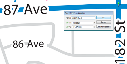
Once the map is open, we can use the Map Locations tool to place reference points or Page Locations on our unreferenced map. It is recommended that known points, or points that are unlikely to move such as the intersections of road ways, are used as reference because these locations will be easily recognizable (as seen in the following steps). Tip: You will also want to zoom in as close as possible to the point to ensure the best possible accuracy.
After we have given a name to our page location we will continue to place page locations until there is four or more spread as evenly across the map as possible. Having greater than four reference locations could help to improve the overall georeferencing accuracy.
The next step is to find the real world counterparts, or World Locations, for each of our Page Locations using the Georeferencer tool. World locations can be sourced from an online map service, an open referenced document or entered manually. In this example we will use the built in Google Maps service to find our World Locations.
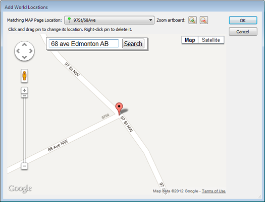
The Google Maps option opens the Add World Locations dialog box. Choose a Page Location from the drop-down list and use the map to find the corresponding world location. Use the Google search bar and zoom buttons to zoom as close as possible to the corresponding world location. Place the cross hairs over the location, click, and confirm the world location with the page location.
If the point is accurate, we will continue to add world locations for each page location. If not, the world location position can be changed by clicking and dragging it to a more accurate location. Right-click the pin to delete it.
If you’re unsure about the position of the original page location, you can drag the Add World Locations dialog box to the side and use the Zoom to artboard tool to help locate it.
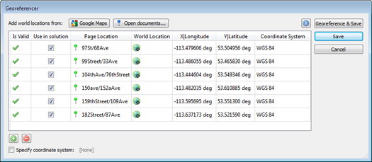
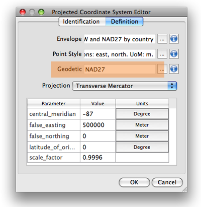
After we have placed all of the World Locations with the corresponding Page Locations, we may now either specify a coordinate system (if one is already known) or click on Georeference and Save.
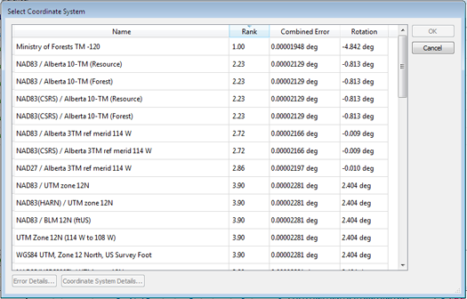
After clicking Georeference and Save, a list of possible projections will be presented. Select the projection which most accurately represents your map. With each projection we see an associated error. This error is based on the combined accuracy of our Page and Map locations.
As in this example, the first ranked projection is not always the best fit for our map, so it is best to use your best judgment when selecting a projection.
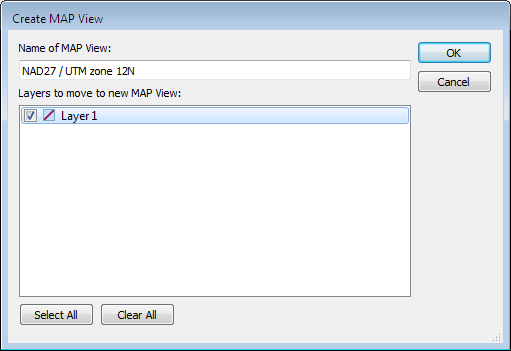
Click OK and add your map to a Map View and save. Your map is now referenced!
We can check the accuracy of our georeferencing by zooming in closely to our Page (green) and Map (blue) locations. The further the distance between the two points, the less accurate a given georeferenced map is.
You can also see a video of the Georeferencer in action on our YouTube Channel.
As we have all seen over the last decade, the distribution and consumption of music, videos and books has moved to a digital model and so, the question then becomes, why not maps? Similarly to the aforementioned media types, maps are also very conducive to both the distribution and use in a digital and mobile way. As we see organizations like Borders, Blockbuster and Kodak succumb to this digital revolution, we map-makers must adapt or suffer a similar fate.
Many of you may be struggling with the issue of selling your maps digitally, tackling the question of the “mobilization” of your content and wondering how to attack the new markets.
But what if there were a generic iTunes/iBooks/Kindle type environment where a map publisher, like many of you reading this, could offer their maps for sale just like musicians and book publishers currently do with their songs and books? There is and it’s called the Avenza Map Store, accessible through the PDF Maps app.
Right now, the Avenza Map Store has more than 100,000 maps from publishers all over the world and we are looking for more as we strive to become the “iTunes of maps”. Map sales in January have already more than doubled December in terms of both units and dollars and December was higher than previous months already.
So here is the gist of the system and the thinking behind it.
What is PDF Maps?
The award winning PDF Maps app is an all-encompassing solution for the use, distribution, and sale of digital versions of paper maps to mobile devices. It includes both an app for users to use, discover and purchase maps directly using their devices as well as an in-app store to facilitate the transaction and delivery of the maps.
Think of it like iTunes, iBooks or Kindle, but for maps.
The app loads georeferenced maps and has functionality for locating (via GPS), measuring, plotting points, importing and exporting points and much more, this goes well beyond traditional paper map usage.
Why PDF Maps? What are the advantages?
The PDF Maps app and the connected map store responds to the demand of both map users and map producers for a 21st century digital map consumption and delivery solution. In an era where a vast amount of content is shifting from analog to digital delivery and use, the map industry demands a similar solution for its users and producers.
For the user it solves four major problems:
How can I use a map I really like on my mobile device instead of the often less-desirable ones Google and other streaming services offer?
Google and other streaming services fail to perform when there is no Internet connection such as when hiking or traveling in remote unconnected areas.
Services that rely on a bandwidth connection are very undesirable when outside your home network area due to the high cost of data roaming charges.
Google and other streaming services, as well as many existing mobile apps, do not always offer a useful map for a particular purpose such as hiking, boating, and visiting national parks which leaves much desire for a “better” map.
For publishers it responds to the following specific needs:
With paper map sales declining, how can I get my content into the digital age for the mobile device market?
Devices like Garmins, TomToms and in-car navigation systems are usually closed to outside map content and thus map producers cannot easily, if at all, make their maps available to users of these systems.
In an effort to get into the digital marketplace it has to be easy, efficient, and inexpensive to repurpose existing content and map libraries. In most cases existing map libraries can be easily ported to the PDF Maps system and existing production processes do not need to be drastically modified, if at all, in order to produce new content for PDF Maps and the Avenza Map Store
With digital map use there is no printing, production quantity guesswork, inventory to manage, distribution and returns to account for.
Updates to the maps are controlled by the vendor and can be instantly made available to the marketplace, while at the same time, older redundant content can be instantly removed and discontinued.
Immediate, easy and effortless entry into the digital map marketplace.
[Video archived] Ted Florence provides a demonstration of the PDF Maps app for iPad. He compares a basic looking Google map of Algonquin Park to a very detailed map of the park which is available on the Avenza Map Store. Combined with using the built-in GPS, it provides a great offline navigation solution.
In addition to showing off the map, Mr. Florence loads a TTC map of Toronto and imports waypoints shared through email. This feature allows for collaboration between people who use the same maps. Importing and exporting waypoints can also be done through Dropbox or iTunes, as demonstrated here. Look for more sharing options in future releases.
After creating a map with MAPublisher or Geographic Imager, you might want to export it as a geospatial PDF file. You want to ensure that the georeference information of your Geospatial PDF files are correct before bringing them into the field for use. A great way to use geospatial PDF maps (and GeoTIFFs) is to load them onto an iPhone, iPad, or iPod touch with PDF Maps installed.
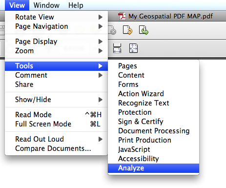
One way to check for georeference accuracy of geospatial PDF files is to use Adobe Acrobat. Open the “Analysis” tool from View > Tools > Analyze.
Click the “Geospatial Location Tool” from the Analyze panel.
With the Geospatial Location Tool enabled, you can see the latitude and longitude values of the map while you move the mouse over the opened Geospatial PDF file.
An important tip you should keep in mind: you need to set the preference option for this tool correctly depending on the coordinate system of the map in the geospatial PDF file.
Open the Preference dialog window:
Acrobat X on Windows: Edit > Preferences > General …
Acrobat X on Mac: Acrobat > Preferences …
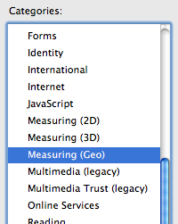
In the Preference dialog window, find the preference category “Measuring (Geo)” from the list of categories.
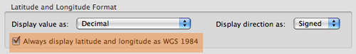
In the “Measuring (Geo)” category, take a look at the right side. There are many options for the georeferencing tool. One of the options is “Latitude and Longitude Format”. In this section, you have a checkbox option “Always display latitude and longitude as WGS 1984”.
This option is very important. If the coordinate system of the map is “NAD 27 / UTM Zone 16 N”, which geodetic system would you like to have to show the latitude and longitude values in Adobe Acrobat? For example, if you are checking the latitude and longitude values in the WGS 1984 geodetic system, you should keep this option selected. However, if you are checking the latitude and longitude values in NAD 1927 geodetic system, then you should de-select this option. The difference in the distance at the same spot between two different geodetic systems may be small or large. If you would like to see the correct latitude and longitude values, you should be aware of this option.
PLEASE NOTE: As of Photoshop 22.5, Adobe has discontinued support for the program’s 3D features. This may affect some or all elements of this blog. For more information, see Adobe’s FAQ page about this change and the Geographic Imager compatibility information page.
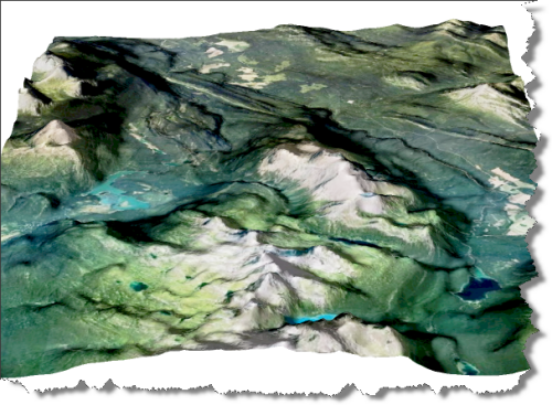
We created a video to show that it is possible to use geospatial data and the 3D capabilities of Adobe Photoshop. It performs very well with a decent computer and video card.
In this video, a combination of Geographic Imager and Adobe Photoshop functions are used to open a DEM file using a script. The script also transforms a DEM into a 3D model and allows for an overlay of a colour model based on the data or a custom image (e.g. ortho image). Video after the jump.
PLEASE NOTE: As of Photoshop 22.5, Adobe has discontinued support for the program’s 3D features. This may affect some or all elements of this blog. For more information, see Adobe’s FAQ page about this change and the Geographic Imager compatibility information page.
NOTE: Prior to performing these steps with your data you would want to ensure that the DEM and image have the same geographic extents.
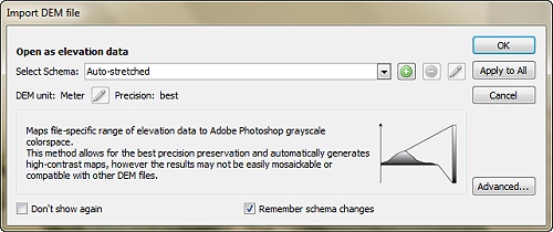
Using Geographic Imager, open your DEM file and set the desired schema type. In this case the DEM was “Auto stretched”.
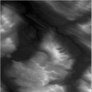
With the DEM now opened and rendered as a 16-bit grayscale Image we can now make use of a number of Adobe Photshop tools to render it in 3D and to drape the image.
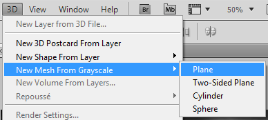
The following steps will outline the Adobe Photoshop procedures required to create the 3D rendition:
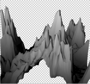
1. Create a 3D mesh: Under the 3D menu within Photoshop select “New Mesh From Grayscle->Plane”
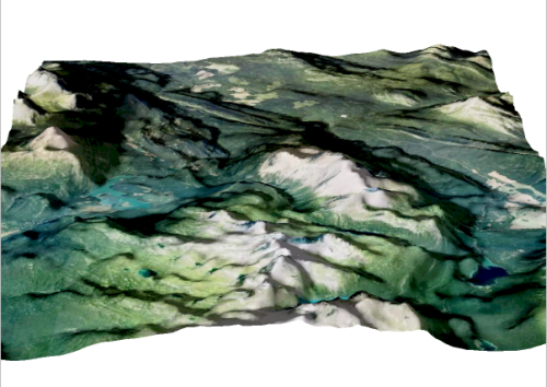
2. We then use the “3D Object Rotate Tool” located in the Photoshop toolbar to manually rotate the mesh tilting it backwards, resulting in something like this
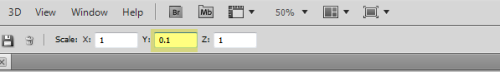
3. The resulting mesh is too exaggerated for a realistic rendering of the landscape so we will adjust the y orientation of it using the “3D Object Scale tool” setting the Y: scale to 0.10
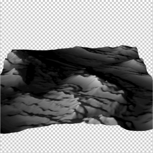
This is the image after vertically rescaling it
4.Once the 3D mesh has been rescaled the image can be draped
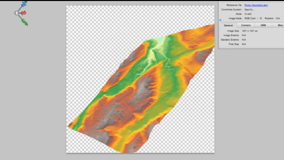
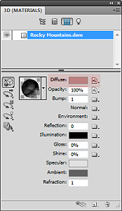
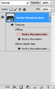
In the Adobe Photoshop “3D Materials” panel, click the “Edit Diffuse texture” button (as denoted in the screenshot below) and select the “Load Texture” option. Now locate and select the image you wish to drape on the 3D mesh.
5. Within the Layers panel turn off the visibility of the Rocky Mountain DEM (as in the screenshot below).
Edit: Updated with a new QGIS workflow (November 21, 2014)
The following tip is courtesy of Hans van der Maarel of Red Geographics.
————-
For many areas on Earth, OpenStreetMap is a viable alternative to commercially offered data sources. However, it is not always easy to process. This blog tutorial explains the steps needed to load OpenStreetMap data into MAPublisher.
1. Download and install QGIS, this is a free GIS application, available for Windows, Mac and Linux computers. QGIS now comes with built in tools for downloading Open Street Map Data.
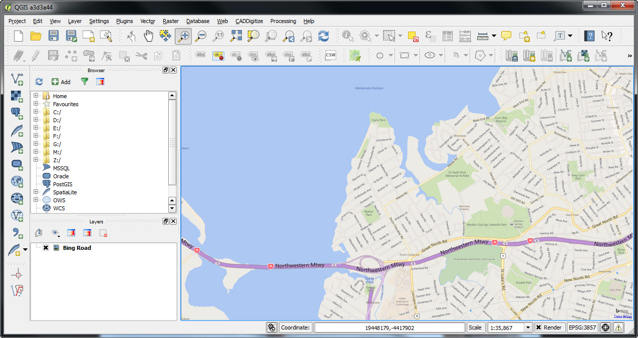
2. Open QGIS and zoom in to an area of interest. Use the OpenLayers plugin for a basemap if you do not have any imagery or mapping of your own. Keep in mind that downloads from the OpenStreetMap website are limited in the number of exported objects, so for larger areas you will have to combine multiple downloads yourself, or look for other options (for example Geofabrik).
Bing Basemap
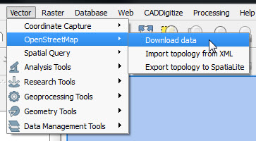
3a. Go to the Vector Menu and Choose OpenStreetMap and then Download data.
OSM Download Menu
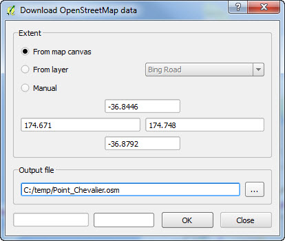
3b. Choose how you want the extent of the downloaded data to be defined. The easiest way is to use the Map Canvas.
OSM Download Dialogue
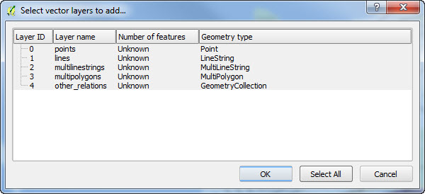
4. Open your downloaded .osm file in QGis using the Add Vector Layer tool. Select all the Layers and choose OK.
Select vector layers to add
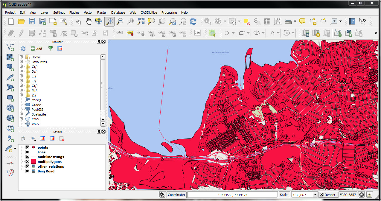
This results are shown in several layers depending upon what is present in the extent you have downloaded. In this case there are points, lines, multilinestrings and multipolygons. Note that QGIS only imports features that fall completely within the extent specified. So make sure you choose an area larger than your actual area of interest to ensure it is completely covered.
OSM layers loaded in QGIS
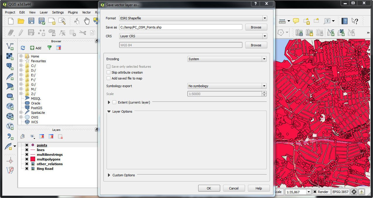
5. Export these layers one by one. Right-click and choose “Save As, then ESRI shapefile”.
Save Points to Shapefile
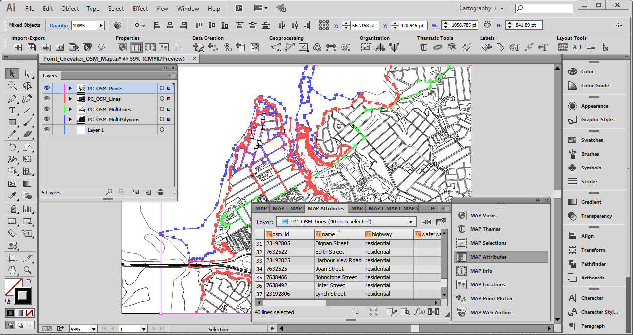
6. The shapefiles can be imported into Adobe Illustrator using MAPublisher. After reprojecting, scaling and cropping we’ve ended up with the raw OpenStreetMap vectors in Adobe Illustrator, with all attributes still maintained.
OSM Layers loaded in MAPublisher
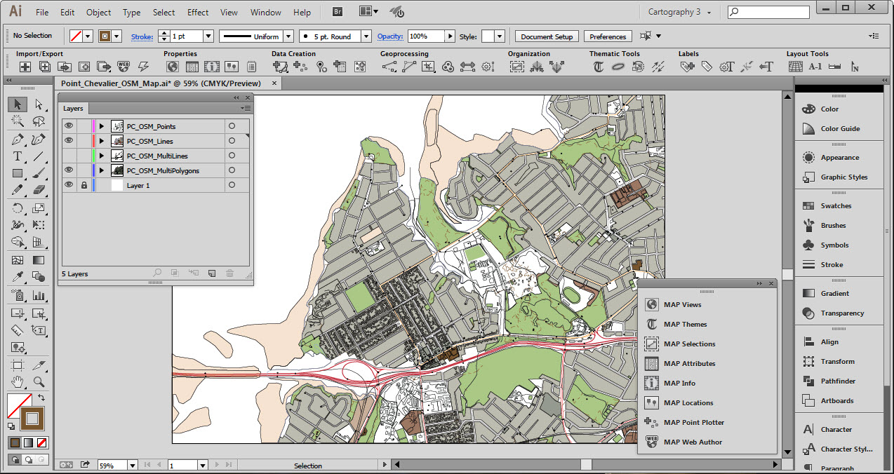
7. Once within the data is imported successfully, you may now use any of the MAPublisher and Adobe Illustrator tools to style and customize the map in any way you want.
Adobe Illustrator documents with GIS data can be exported to georeferenced PDF files thanks to the MAPublisher Export Geospatial PDF feature. A geospatial PDF is an Adobe Acrobat file that contains geospatial coordinates. With coordinates, users can view and interact with the PDF to find and mark location data. MAPublisher exports all the MAP Attributes data in an Adobe Illustrator document into the geospatial PDF. Attribute values can subsequently be accessed and searched in Acrobat 9 (and 8 with limitations).
In order to ensure the best interoperability and geospatial PDF output results from your MAPublisher documents, the following work practices are recommended:
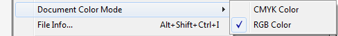
Convert document color mode to RGB
To ensure predictable color results, it is highly recommended to convert the documents color mode to RGB prior to exporting to Geospatial PDF. This is advisable especially if generating geospatial PDF documents to be used in conjunction with the PDF Maps app for IOS devices. The document color mode can be changed in Adobe Illustrator through File > Document Color Mode > RGB Color.
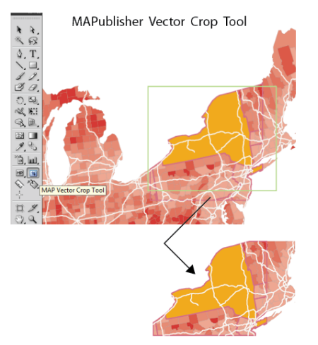
Crop data to the required extents using the MAP Vector Crop Tool
Remove any extraneous data not required for the geospatial PDF document by cropping the map using the Vector Crop Tool (located in the Adobe Illustrator Toolbar). If necessary, exclude data from being cropped by locking the its the appropriate layers.
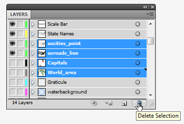
Remove unnecessary layers
Delete any map layers that are not required for the final PDF map document. This may include raster layers, hidden layers, and layers that are outside the mapping extent or art board. Not only will this decrease file size, it will also simplify your layers list and improve organization. Delete layers in the MAP Views panel or the Layers panel.
Preserve data contained within sublayers
If your document contains map data organized within sublayers it will be necessary to reorganize/move this data to it’s parent layer if you wish to preserve it when converting to and from geospatial PDF. This is necessary because data contained on sublayers are forced into their parent layer by the Adobe Illustrator PDF exporter. Layers are also required for importing a geospatial PDF back into MAPublisher in order to assign a schema.
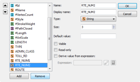
Remove unused attribute information
Data sets, especially those available through various data portals and government agencies can contain attribute information not suited or required for our mapping need, or perhaps we are only interested in the geometry of the data for representational purposes. In this case it is advisable to delete any attribute information that does not fulfill a purpose as this will unnecessarily increase the resultant file size. Select your data, open the MAP Attributes panel, and click the Edit Schema button. You may delete and organize your attributes using this panel.
Assign MAPublisher attributes to Adobe Illustrator Object names
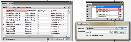
This recommendation is not necessary but may be useful in some cases. In MAPublisher the #Id attribute column is a unique identifier MAPublisher uses internally to associate attributes with unique pieces of art. By default the art will have a name of “path” or “compound path” however it may be desirable to tag the object with a unique identifier from an existing attribute column for the purposes of making it easier to differentiate art objects within the Acrobat tree list, for example.
To do this we can use the “Apply Expression” option in the MAP Attributes panel. Simply designate the #Name column as the “Apply to” option while entering the name of the attribute column you wish to derive the attributes from as the “Expression”. For example in the screeshot below we are renaming the art objects contained in the #name column with values stoed in the “ROUTE” column with the results being reflected in the artwork listed in Illustrator Layers panel.
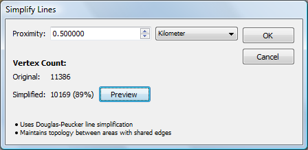
Use the Simplify Line Tool
Reduce the number of vertices available in MAP Line and Area layers by using the Simplify Line tool (located on the MAPublisher toolbar). This differs from the Adobe Illustrator Simplify Path tool because it takes into account X and Y coordinates. The proximity value or simplification tolerance is based on the vertical difference between the begin-end line and points off a line, not the distance between anchor points on the line.
Geospatial PDFs derived from or include images should be generated as 72 DPI
This has particular relevance when dealing with geospatial PDF files, especially those generated with Geographic Imager. When a 200 DPI (dots per inch) georeferenced image is converted to a geospatial PDF, the image will be embedded in the PDF as a 200 DPI image. However, when displayed by PDF viewing applications such as Acrobat or Illustrator it will appear as a 72 DPI image. Due to this, on export, MAPublisher converts the referencing to 72 DPI format since it must be imported back as 72 DPI
Following the above recommendations should help ease the transition of your MAPublisher documents to and from geospatial PDF.
Dot density themes are sometimes called dot distribution maps because they show where particular data characteristics occur. It uses dots or other symbols to represent the number of occurrences of a given data characteristic in a particular location. Starting at MAPublisher 8.4, the ability to create dot density maps is available through the provision of Dot Density Themes.
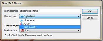
When creating a new MAP Theme simply choose “Dot Density” from the available theme types. The creation of a dot density theme is facilitated through the MAP Themes panel. The dot density theme is an Adobe Illustrator effect applied to an area layer.
As dot density maps are most useful for showing where particular data occur, they may only be generated for MAP Area type layers. Most often, symbols are used to represent data occurring within a bounding polygon such as a census tract, zip code or county polygons.
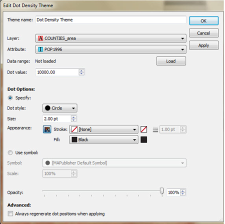
Dot density effects are created on a per layer basis, based on various user defined settings. Data ranges can be determined from selected attribute columns and then a dot value can be assigned a corresponding symbol at which point MAPublisher will map the appropriate results. Users may apply default symbols or load custom ones based on Illustrator symbol sets
In this example, population tallies per county have been loaded, assigned a dot value of 10,000 with a designated symbol of a 2pt black dot.
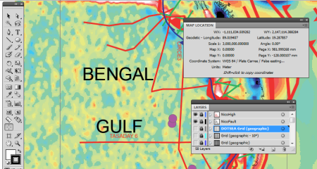
This screenshot displays the map prior to applying the dot density effect.
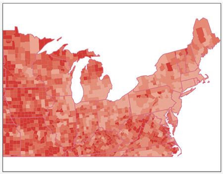
The screenshot below displays the map after having applied the Dot Density Theme using the parameters displayed within the dialog .
New to the MAPublisher 8.4.2 Make Index tool is an enhancement that allows you to index objects relative to a MAP Area layer’s features instead of an index grid. This new functionality compliments the existing geoprocessing tools found in the Buffer Art tool and the Spatial Filter in the MAP Selections panel.
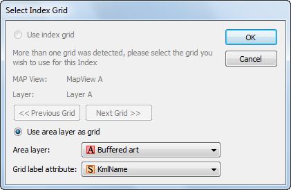
An index grid on a MAP Legend layer is no longer a prerequisite for using the Make Index tool. By choosing the “Use Area layer as grid” option in the Make Index dialog box, a spatial query will be performed and an index file will be produced based on the layer and attribute specified.
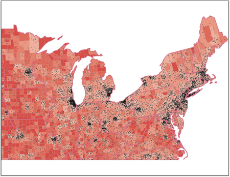
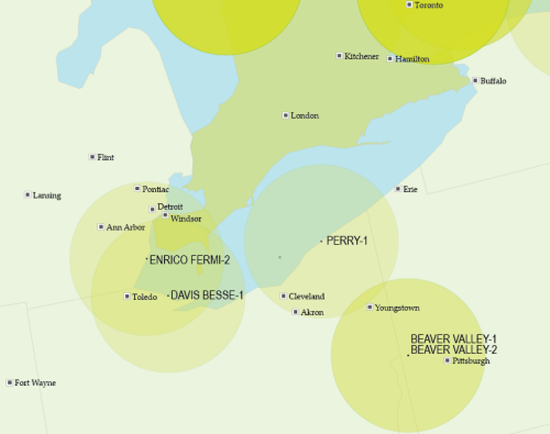
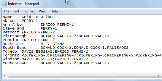
For this example, I have loaded a point file of cities and a point file of nuclear facilities against a background of North America. I then proceeded to use the Buffer art tool to create 80 kilometer buffers around each facility.
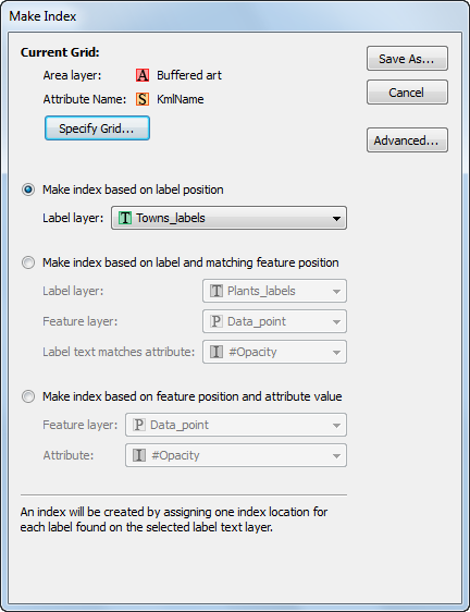
Finally, I will produce an index that returns which communities fall within the 80 km radius surrounding each nuclear facility. For this index I will choose my Towns_labels MAP Text layer.
With these settings our index gives a line for each city that falls within the buffer, and after a tab delimiter, gives the name of each facility as found in the kmlName attribute of the Buffered Art layer. Notice that for cities that fall within the buffer of multiple nuclear facilities, the values from the kmlName attribute field are concatenated together with a semicolon “;”.
If you choose to make an index using an index grid, the option to add an attribute from a bounding MAP Area layer can be accessed from the Advanced tab of the Make Index dialog.
Currently, MAPublisher and Geographic Imager are NOT officially compatible with macOS Tahoe. To avoid any potential issues, please refrain from updating to macOS Tahoe at this time.